
Schmiede19 MIDILAB
This post developed during the DIY MIDI controller workshop at Schmiede 2019 in Hallein (Austria). It was used as a presentation and documentation tool.
What can we do with MIDI?
- Play notes
- Change parameters
- Change programs/presets
- …
What is MIDI?
- a serial communication protocol
- bitrate of 31250 bps (bits per second), also called “baud rate”
- each message consists of 2 or 3 bytes
MIDI messages
| Value (dec) | Value (Hex) | Command          | Data bytes                |
| ------------| ----------- | ---------------  | ------------------------- |
| 128-143     | 80-8F       | Note off         | 2 (note, velocity)        |
| 144-159     | 90-9F       | Note on          | 2 (note, velocity)        |
| 160-175     | A0-AF       | Key Pressure     | 2 (note, key pressure)    |
| 176-191     | B0-BF       | Control Change   | 2 (controller no., value) |
| 192-207     | C0-CF       | Program Change   | 1 (program no.)           |
| 208-223     | D0-DF       | Channel Pressure | 1 (pressure)              |
| 224-239     | E0-EF       | Pitch Bend       |                           |
| ------------| ----------- | ---------------- | --------------------------|
16 MIDI channels
Note byte 1 (channel):
- Channel 1: 144
- Channel 2: 145
- Channel 16: 159
Note byte 2 (note number):
C0  = 0
C1  = 24
C#1 = 25
C4  = 60
A4  = 60
C5  = 72
another MIDI note numbers list
CC message:
- Channel 1: 176
- Channel 2: 177
- Channel 16: 191
Examples
Send a NoteOn message for the note of D#3 on channel 1 with a velocity of 90:
144 | 36 | 90
Send a Control Change message for Controller number 81 on channel 2 with a value of 65
177 | 81 | 65
Can we choose any CC number for our controller?
Getting to know the hardware
official Arduino specs comparision table
Nano pinout

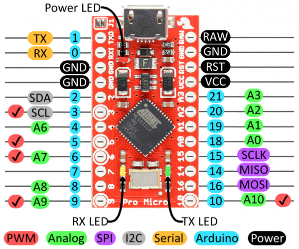
Pro Micro pinout
Nano specifics
The Nano is very similar to the well-known Arduino Uno, it only is smaller and has more connection possibilities.
Chinese Nano clones (CH340)
The Arduino Nano clones we use, have a CH340 chip that does the USB to serial conversion. To program it we need a USB-driver specific to our computers operating system.
For Mac OS X High Sierra and above we need this driver
For Windows 10 we need this one
Programming settings
Golden USB socket version:
- Board: Arduino Nano
- Processor: ATmega328b
Silver USB socket version:
- Board: Arduino Nano
- Processor: ATmega328b (old bootloader)
Both types:
- Select the correct serial port
- Mac OS X: something called /dev/cu.something (eg. /dev/cu.wchusbserial1410)
- Windows: COMx (eg COM4, COM10, …)
- use the Devicemanager to find out which COM port appears when you connect the Arduino to the USB port
If our programming settings or the CH340 driver are wrong this is one of the possible errors:
avrdude: stk500_getsync(): not in sync: resp=0x00
Pro Micro specifics
Sparkfun Pro Micro hookup guide
nice Pro Micro connections video-tutorial, also about multiplexing input
Chinese Pro Micro clones
Specifically this chip: ATmega32U4 5V 16MHz
Programming settings
- Board: Arduino Leonardo
- Select the correct serial port
- Mac OS X: something called /dev/cu.something
- Windows: COMx (eg COM4, COM10, …)
- use the Devicemanager to find out which COM port appears when you connect the Arduino to the USB port
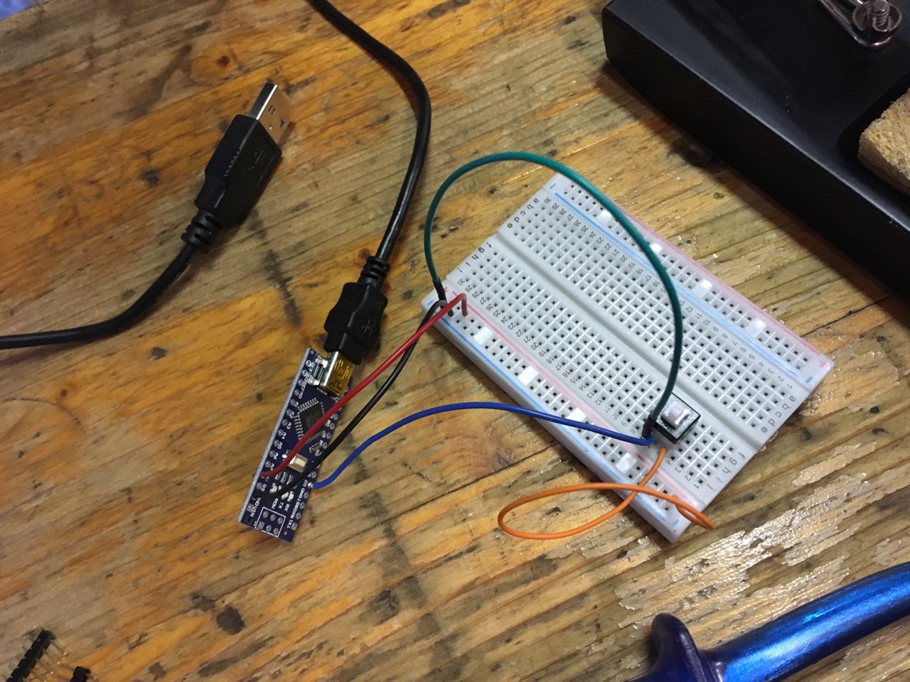
Wiring power connections and a button
To power the plus- and minus-rails of our breadboard we connect the 5V and GND pins to it. On the Pro Micro the 5V pin is called VCC.
So why is position and wiring of the switch wrong?
The short answer is: Because we assumed that these switches work similar to a lot of other switch types.
The square-button-switches we use are so called DPDT switches (Dual Pole Double Throw). This basically means that we can use them to switch on/off or toggle two things with one buttonpress. Or put differently: Two switches in one.
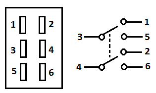

Let's assume the same pin numbering as on the regular DPDT diagram on the left, for our oddly wired switches on the right: In off-state 1+5 and 2+6 connect. In on-state it's 1+3 and 4+6.
So what actually happens when we plug in the power to the breadboard (connect the Arduino to a USB port) and keep the button unpressed, is: We connect + and - poles together (via pins 1 and 5) and thus short-circuit the Arduino which it can withstand for a short time only.
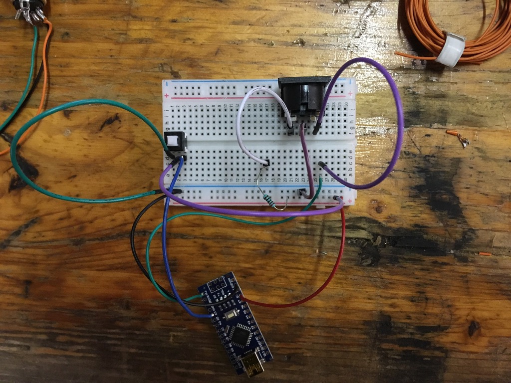
To correctly wire these types of switches we need to:
- plug them into the middle of the breadboard so the two 3-pin-rows aka the 2 switches are isolated from each other.
- use pin 5 (bottom-right / blue wire on pic below) to connect to the Arduinos input (D2).
- in unpressed state pin 1 (bottom-left / green wire) and pin 5 are connected and thus D2 is connected to GND
- in pressed state pin 1 (middle / purple wire) and pin 3 are connected and thus D2 is connected to 5V.
Wiring the MIDI socket
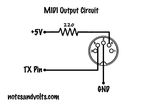
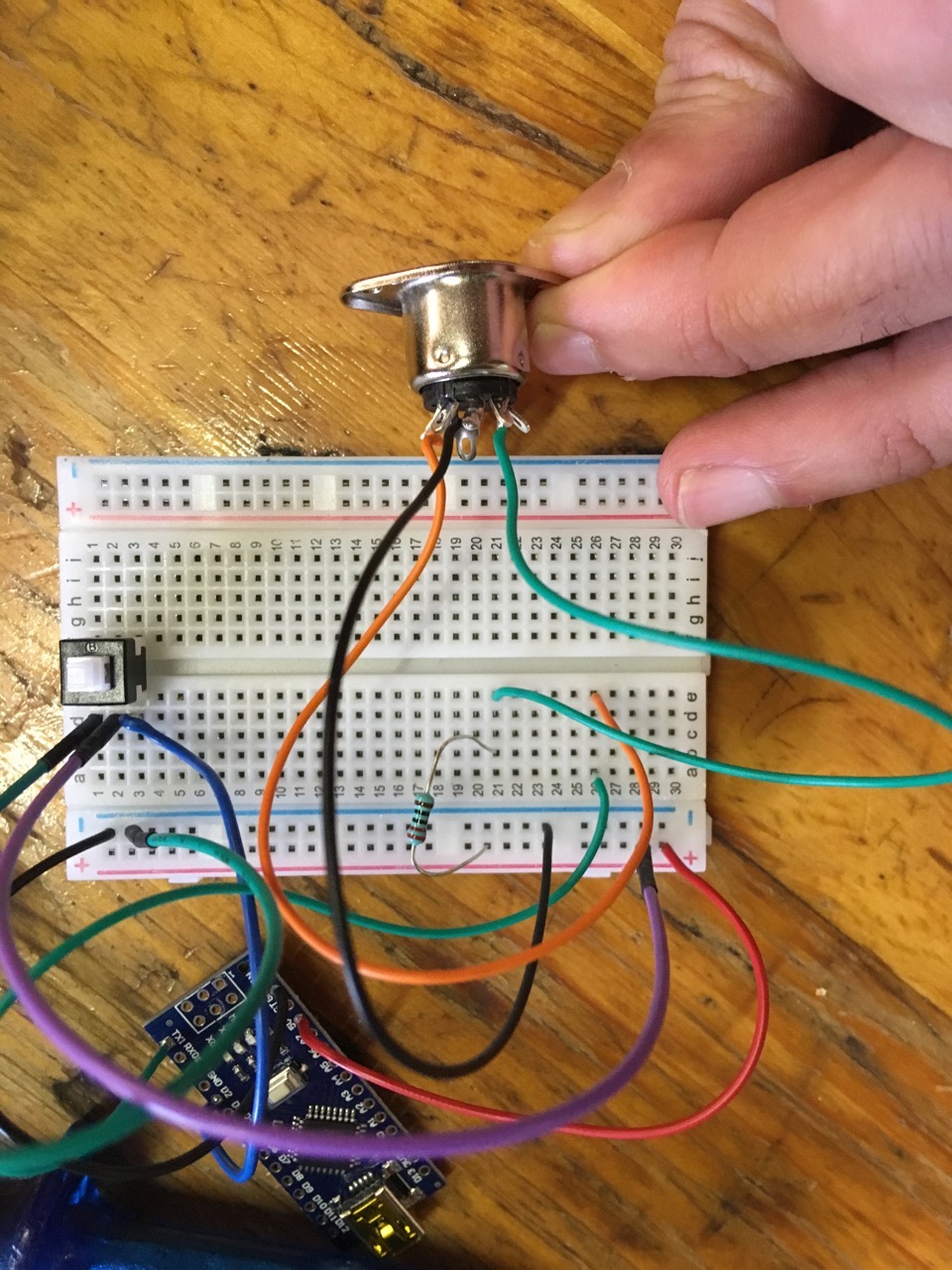
For more detailed schematics and information on MIDI Output and MIDI input wiring refer to the official MIDI specification of the MIDI manufacturers association
Wiring a potentiometer
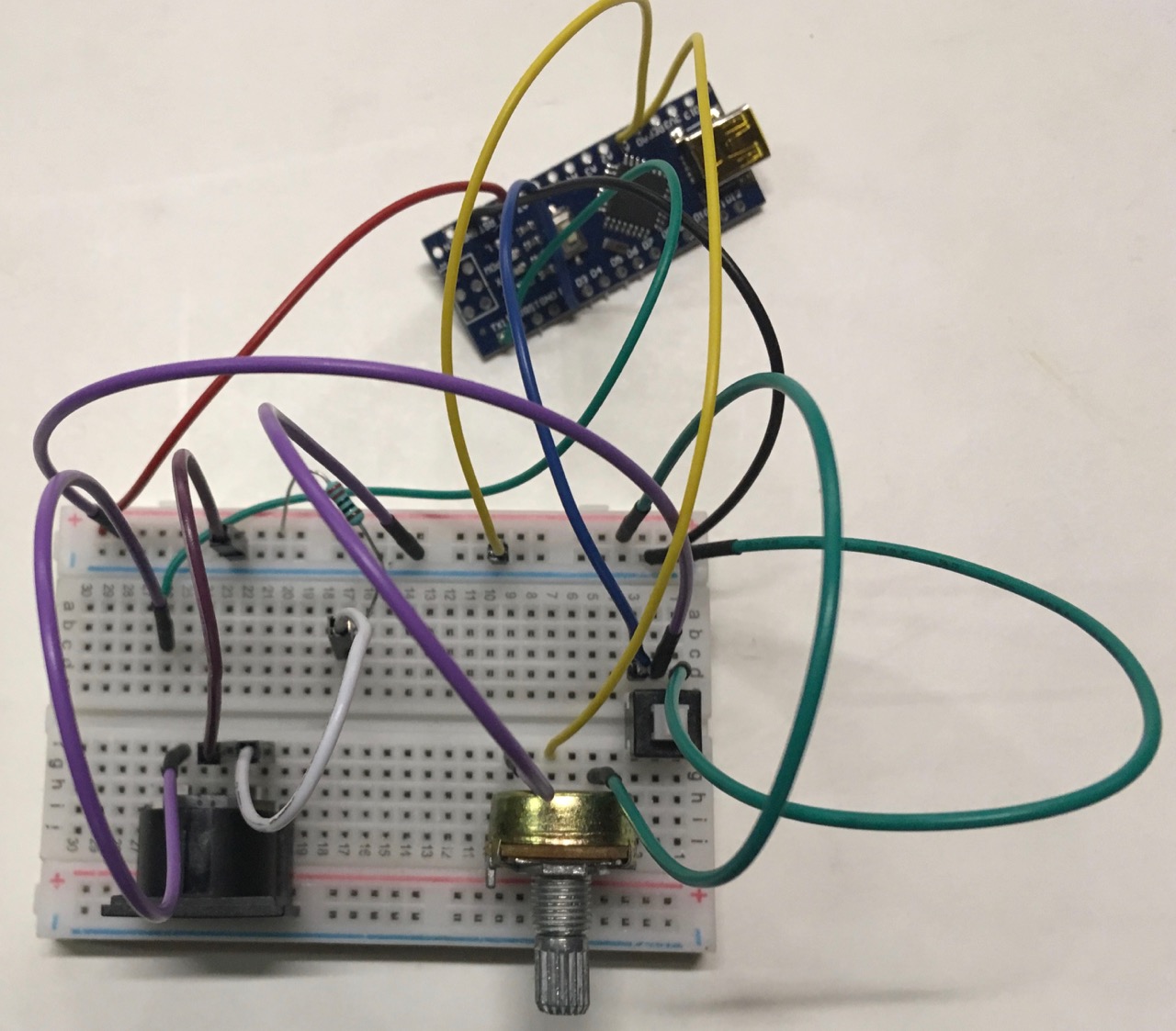
When we twist the knob to the left we decrease the resistance between ground (purple wire) and the pots output (yellow wire) until it is 0 Ohms. When twisted to the right the resistance between the two wires increases until it reaches almost the nominal value of the pot (10kOhms). The actual Ohms are not of interest when using pots with Arduinos. When we read out the current value of an analog input we always receive a number between 0 and 1023
There is a second yellow wire that is supposed to be connected to a second pot but for now we put it on ground so the Arduinos input A1 does not deliver measuring values and disturb us while coding and/or debugging.
Coding
The code we produce is available on this github repo
Direct links to “git commits”:
final code day 1 - reading in a button’s state
final code day 2 - sending out midi CC on and off
day 3 - four switches for-loop example
day 3 - two pots for-loop example