
Building MIDI controllers #1 - The Matrix
MIDI controllers are not the most complicated things on earth to build and program.
If you have your MIDI basics covered and have a little experience with Arduino-type microcontrollers it’s just a matter of capturing an inputdevice (button, knob, …) into your microcontroller and sending some bytes out via a serial port, which MIDI essentially is.
There is a lot about building basic MIDI controllers on the net already so I won’t cover that, but give an overview of what helped me to get going:
- This is probably the best explanation of how MIDI circuits really work from an electrical point of view.
- This basic MIDI controllers tutorial is from the same guy but unfortunately he doesn’t explain much how it actually works, you won’t learn coding with this one.
- Video series in german language for absolute beginners without any Arduino experience. Also he doesn’t use any libraries but explains how to do everything from scratch. Valuable!
- This video is quite nice, he’s using a Teensy microcontroller which has MIDI over USB by default
Speaking of: just to get one slightly dissapointing thing straight from the beginning: Most of the common Arduino types are not capable of natively spitting out MIDI on their USB ports, but I’m going to show a hardware-hackish approach to still make it work. A few Arduinos have native USB capabilities and can make use of the MIDIUSB library , but that’s usually the type of Arduino you don’t have at hand at the right moment. The only one’s that have USB-MIDI out of the box are the Teensy’s but they cost a little more, if you don’t want any hassle go get one! This is the website of the founder, you’ll find excellent documentation there.
The input device
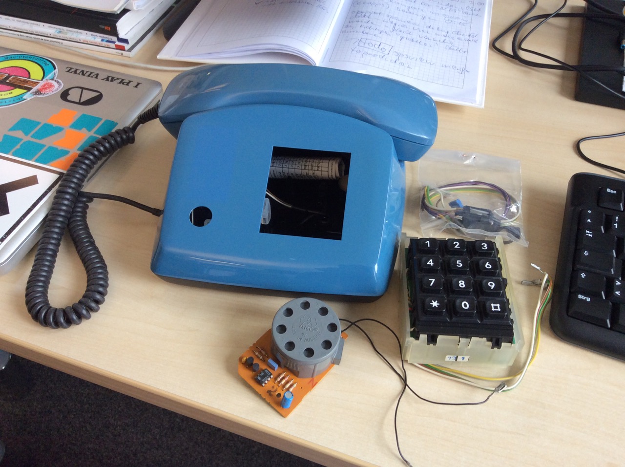
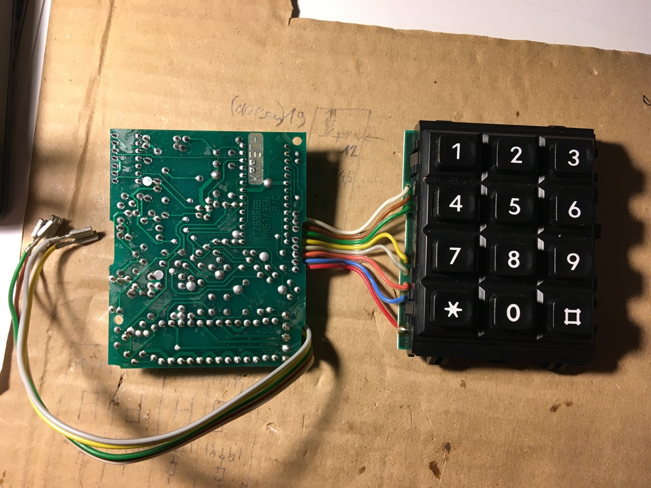
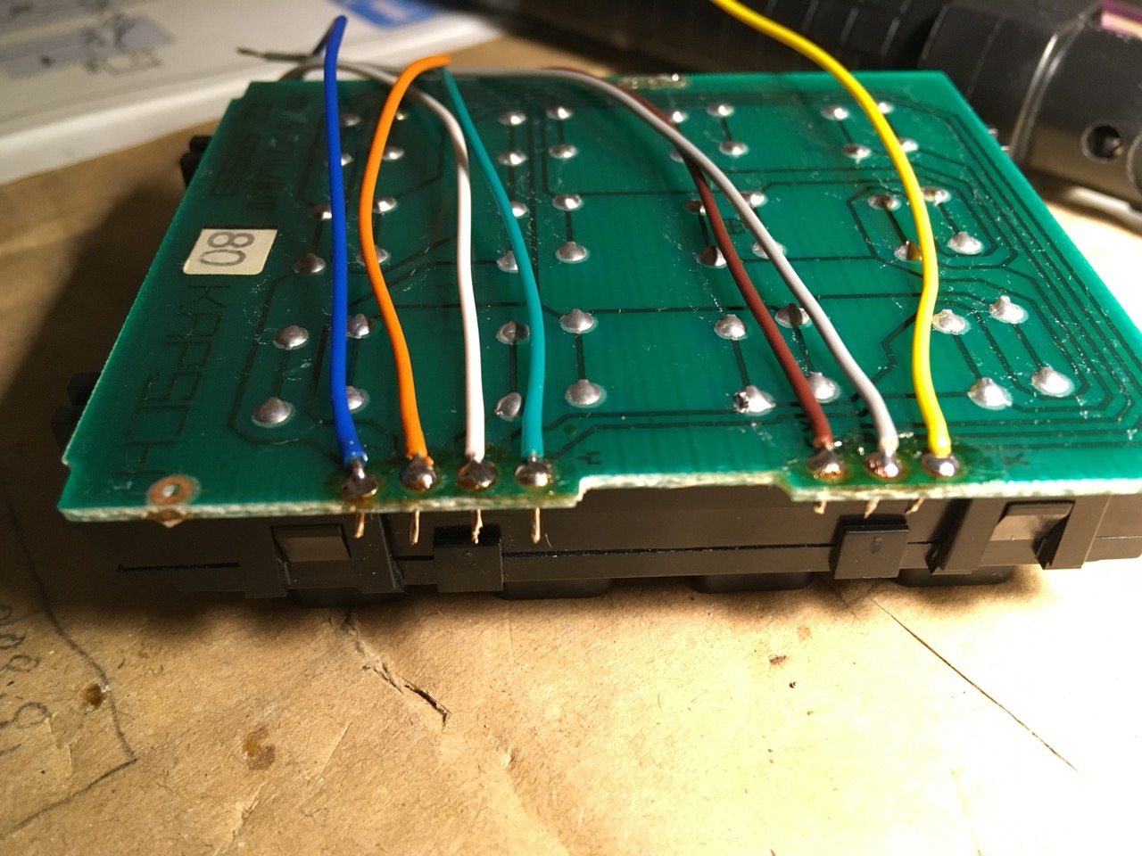
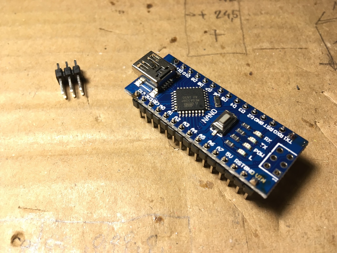
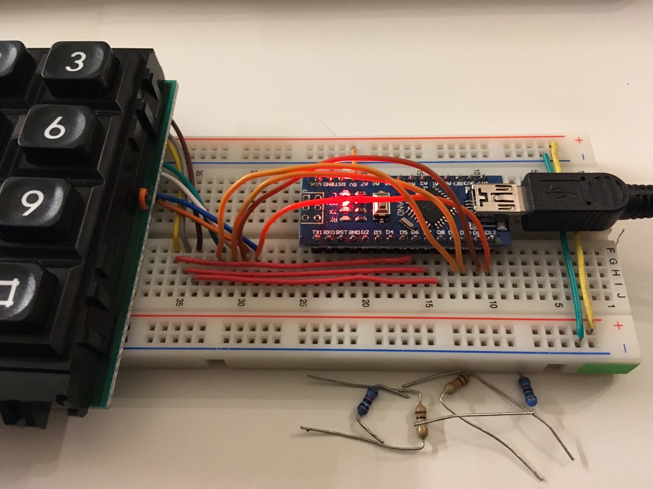
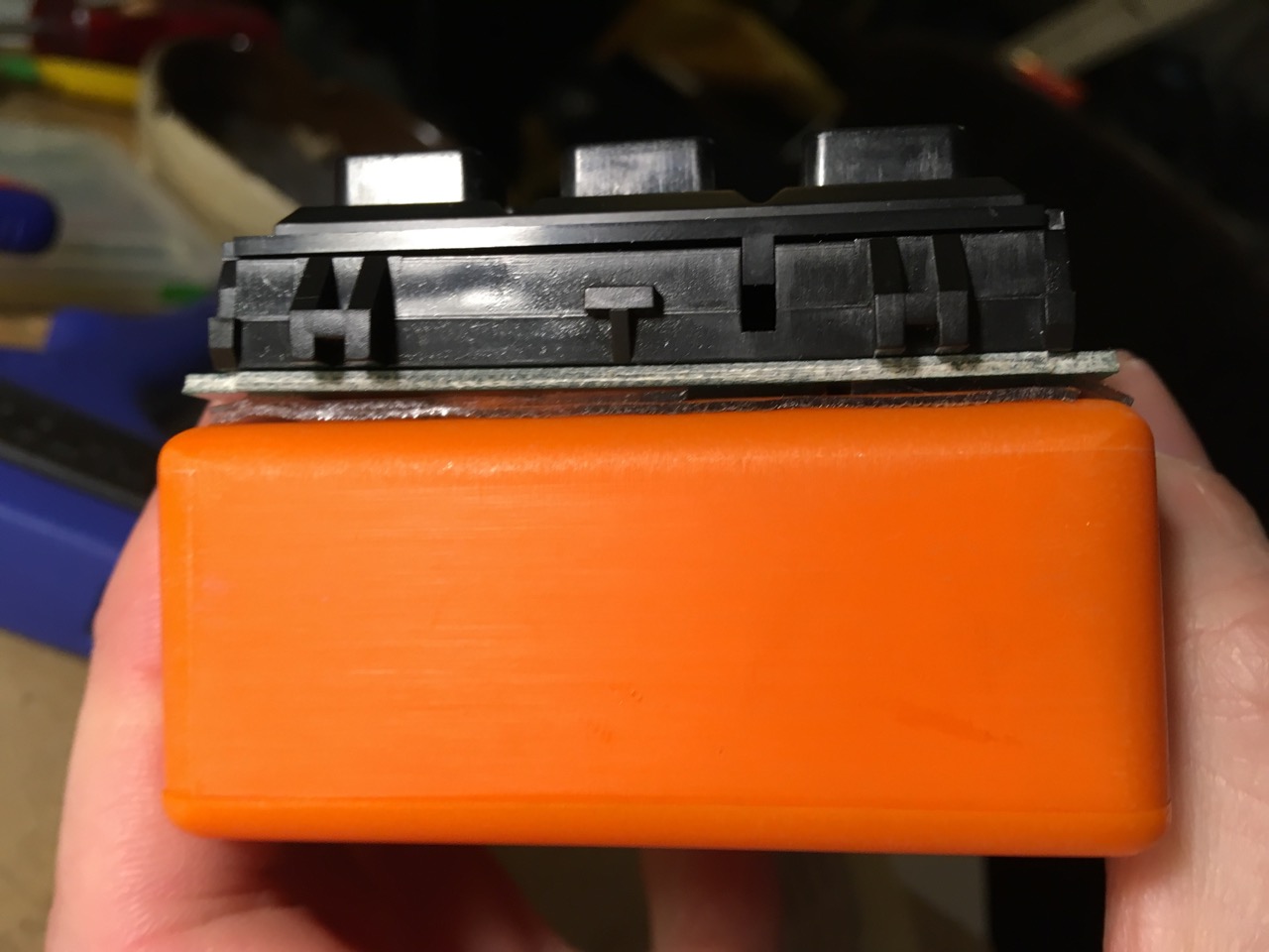
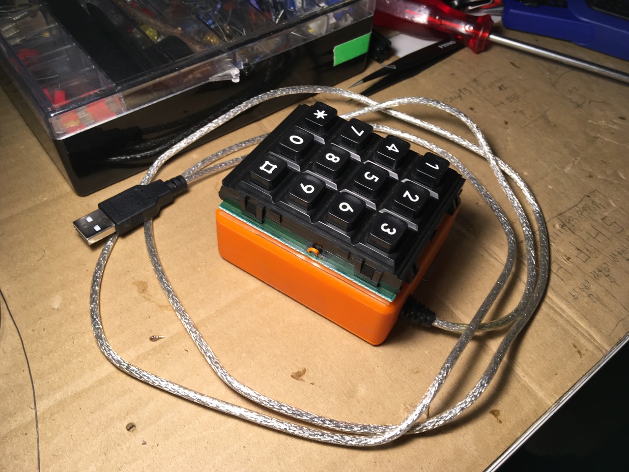
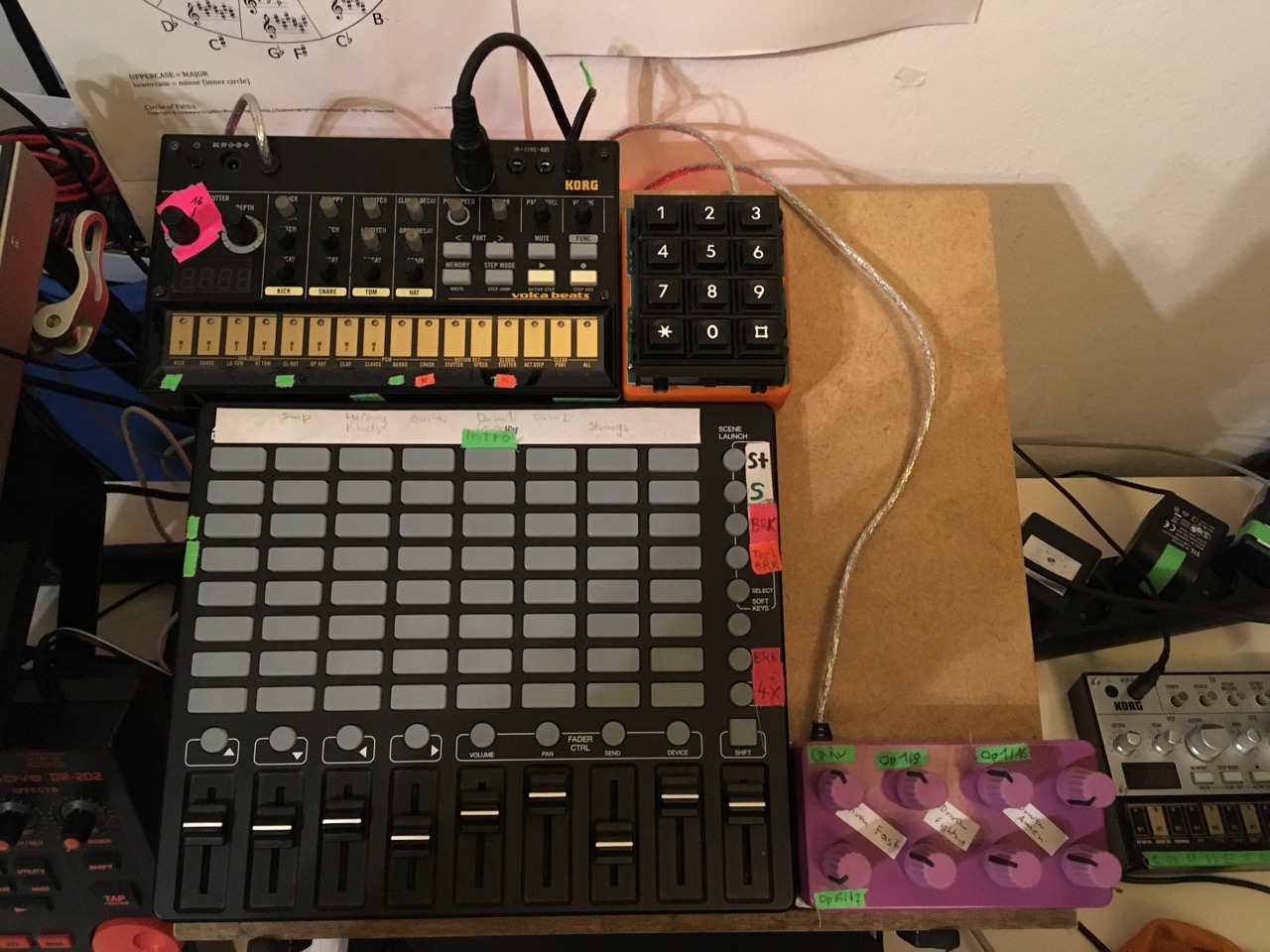
This is going to be my chosen input device, a button matrix out of a 1995 landline phone, built by the company Kapsch, model TP80.
Understanding
So wtf is a key matrix? This guy explains it quite well, just ignore the voltage ladder for now. The german speaking guy over here, altough a bit more advanced, is explaining useful things too. He uses a button matrix out of an old chipcard terminal.
Personally my first experience with a button/keyboard matrix was the tiny 80s keyboard featured in one of my blog posts. I found a lot of information about a similar keyboard on this website. The site owner even has put together a whole FAQ about circuit bending and especially hacking keyboards. Scroll down a little (well a lot, it’s long) and look for headlines containing keyboard matrix. Deadly useful information there!!!
If it still all doesn’t add up, check this and certainly wikipedia
Measuring
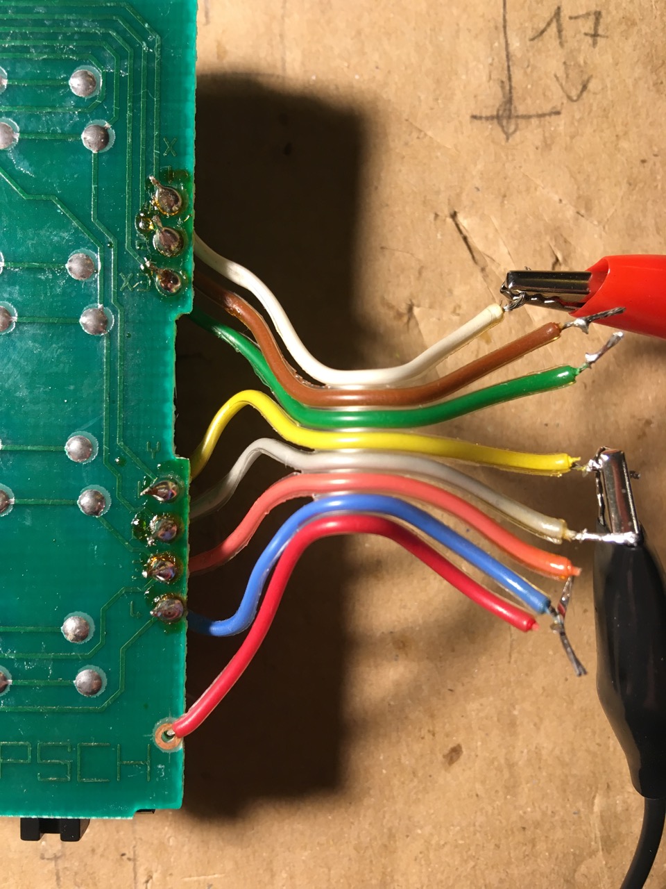
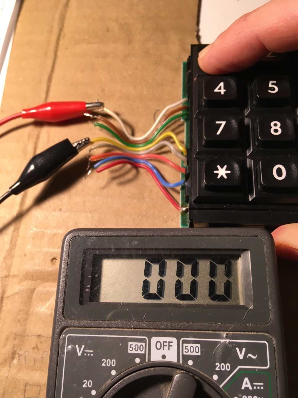
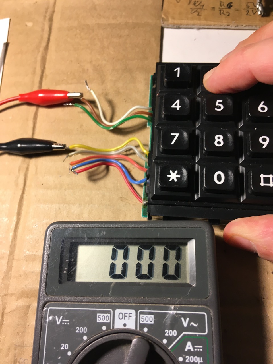
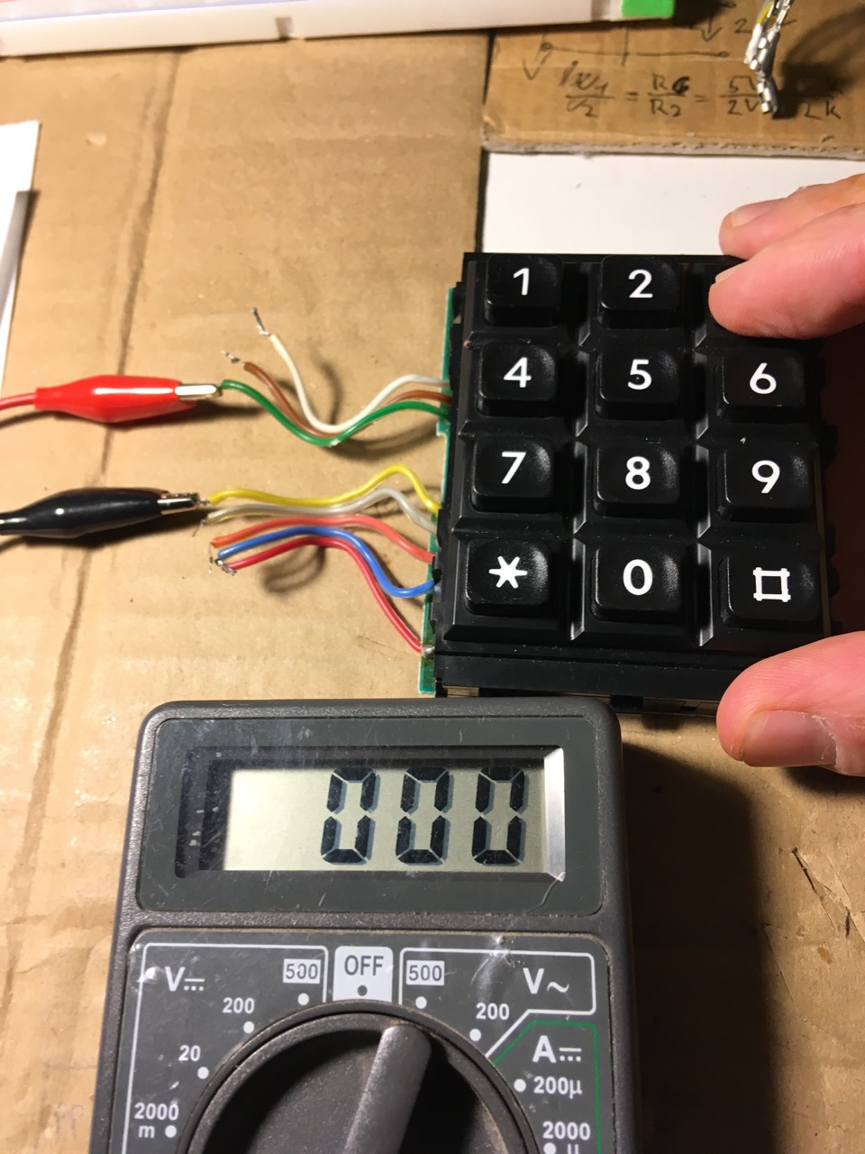
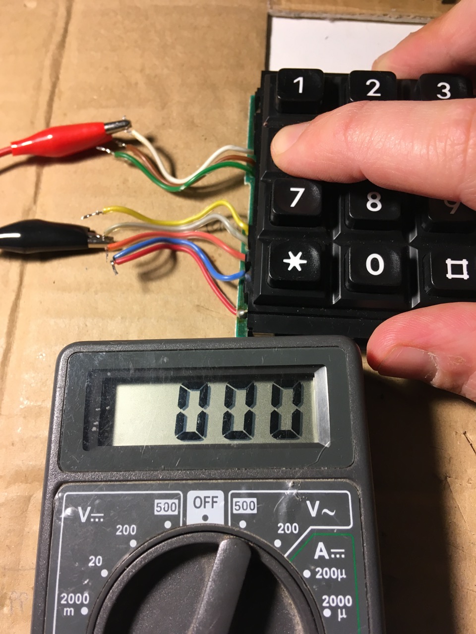
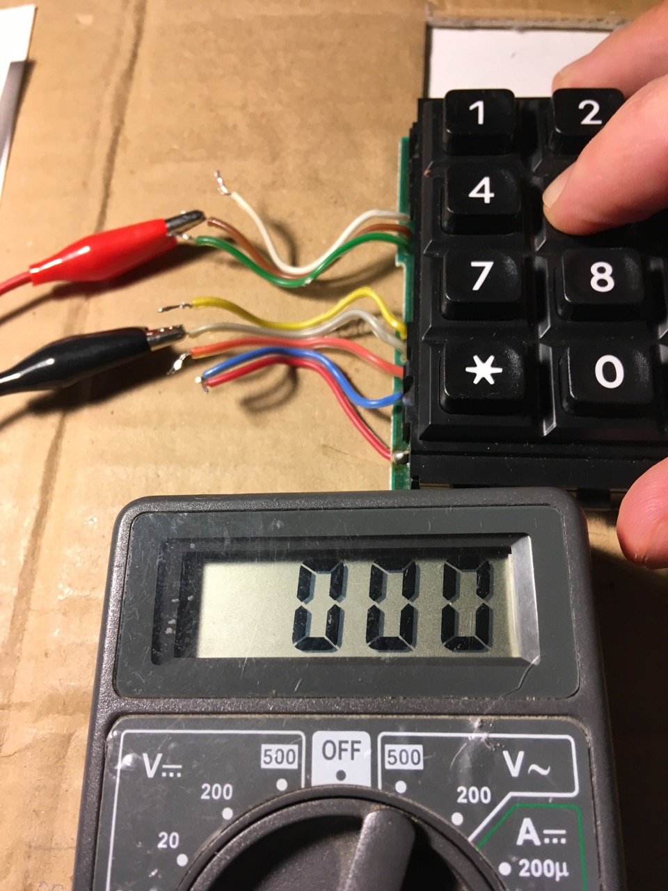
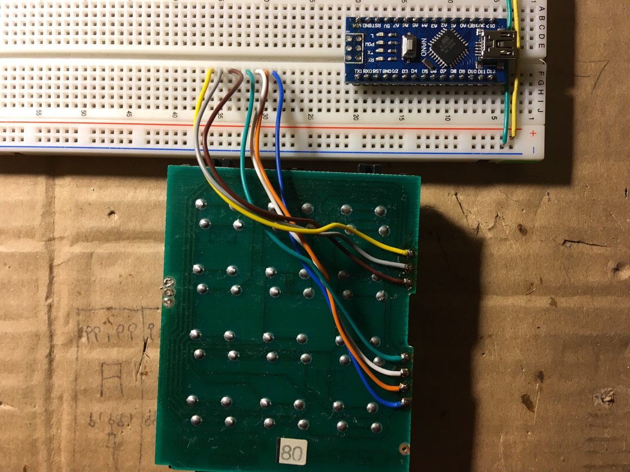
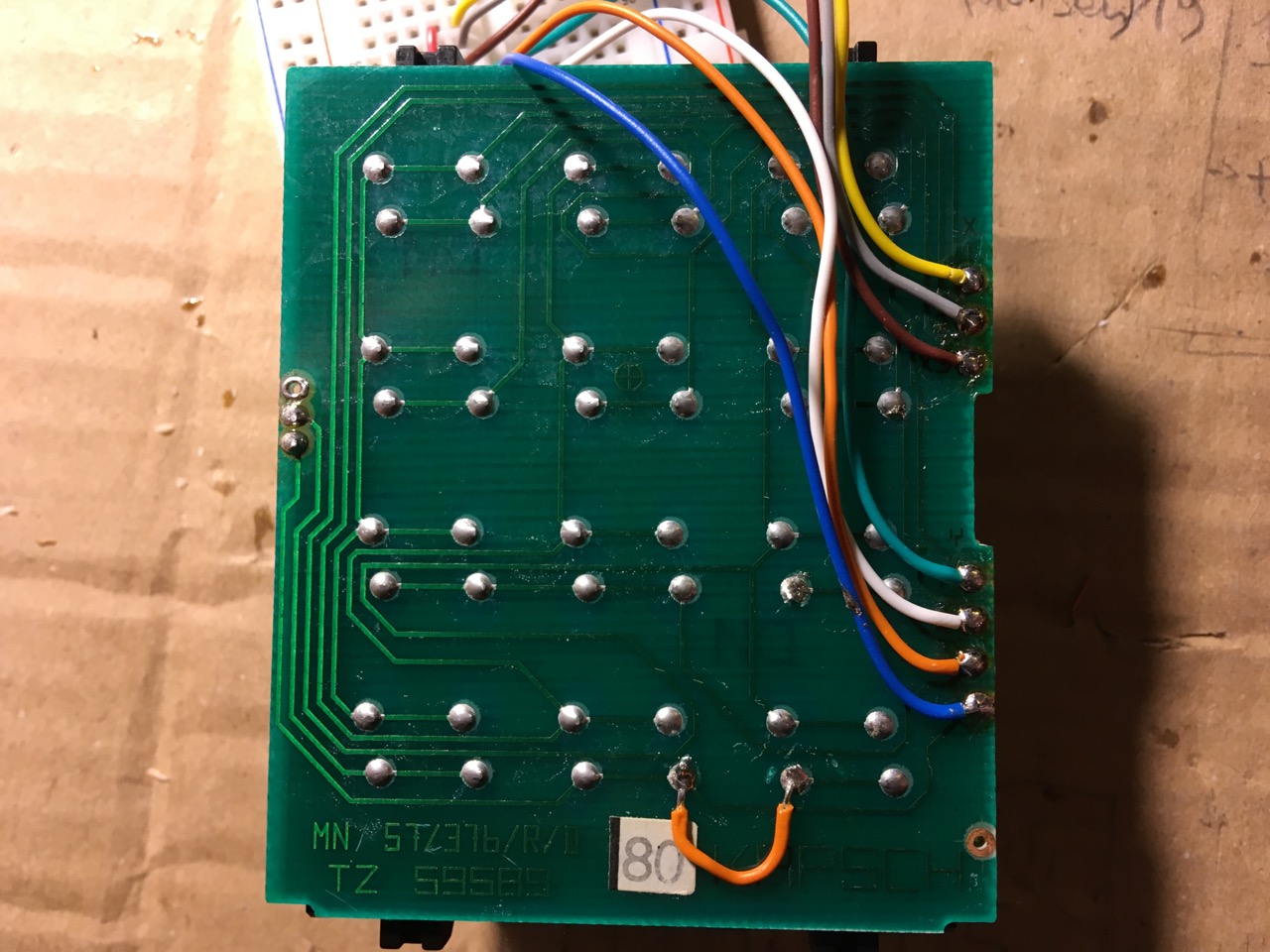
I guess you see where this is going by now. If not, go back and rewatch the youtube videos an links posted above. Ok, so we can think of our matrix that it has 3 column lines, the X-wires, and 4 row lines, the Y-wires.
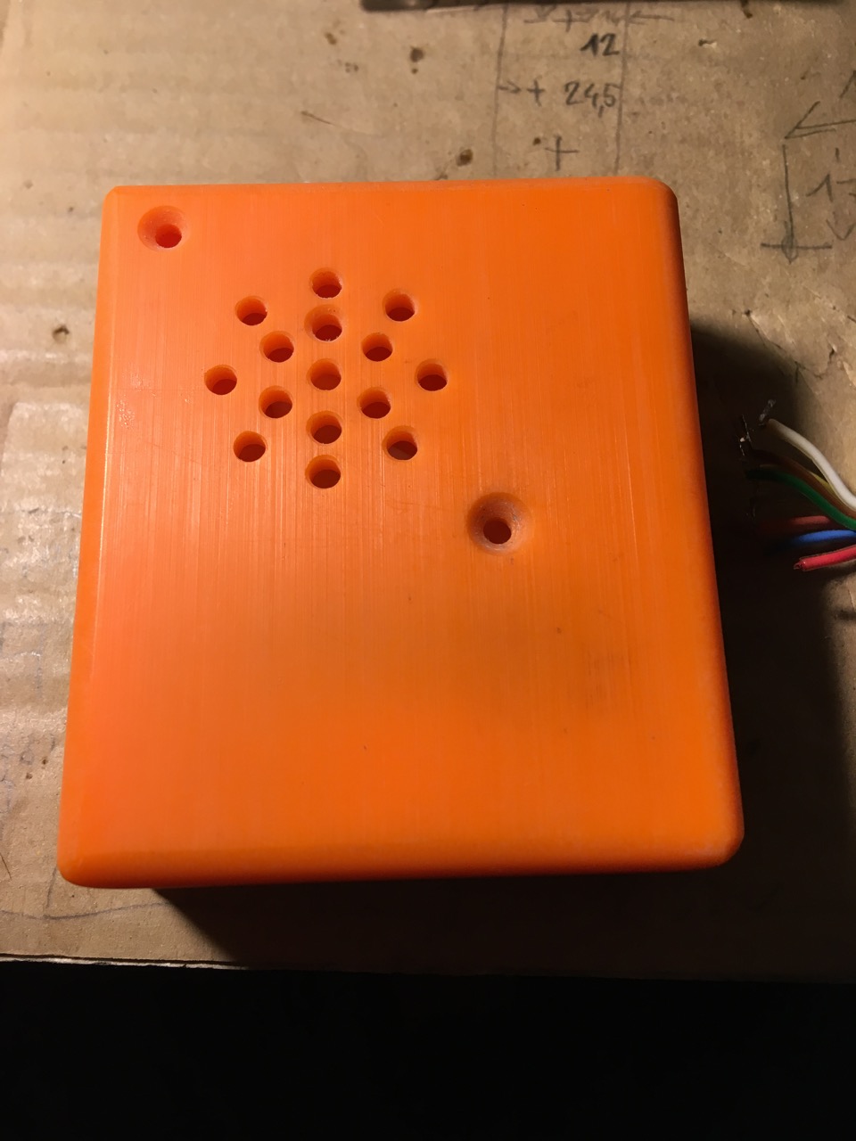
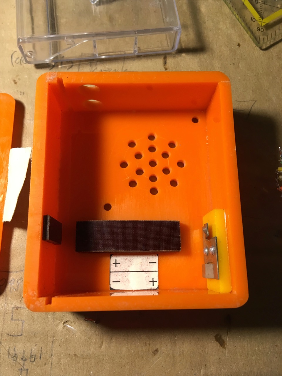
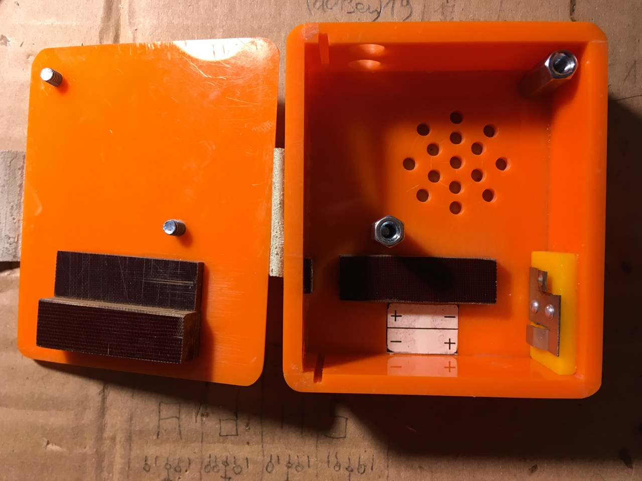
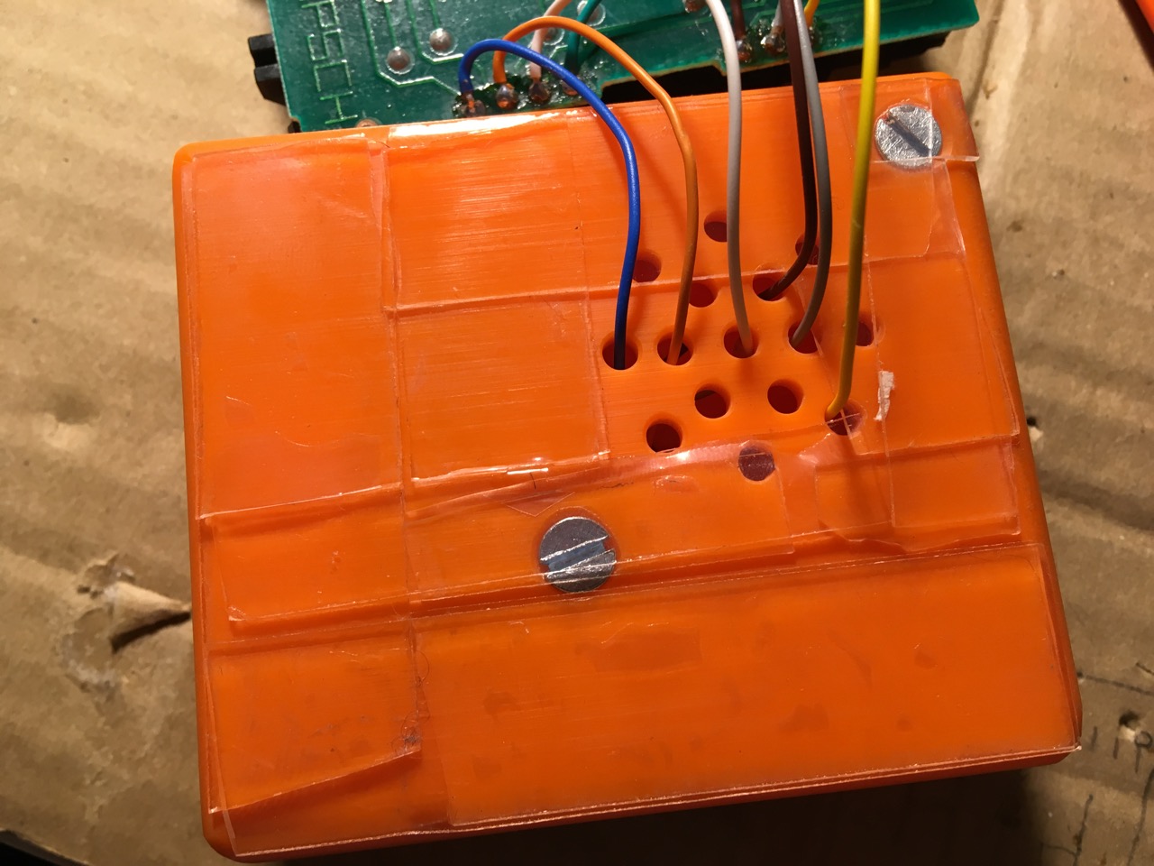
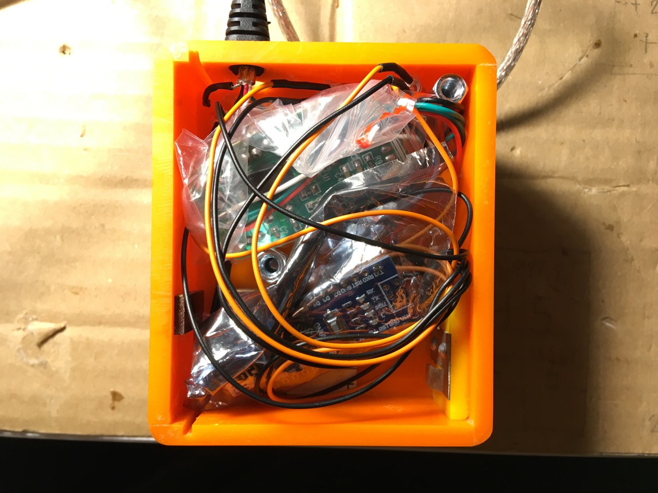
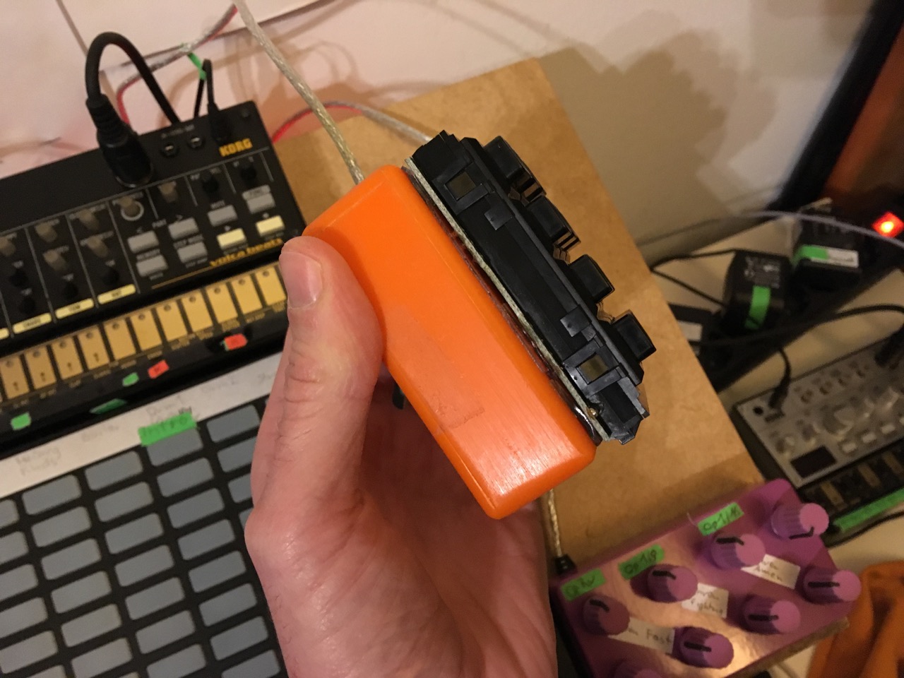
Housing
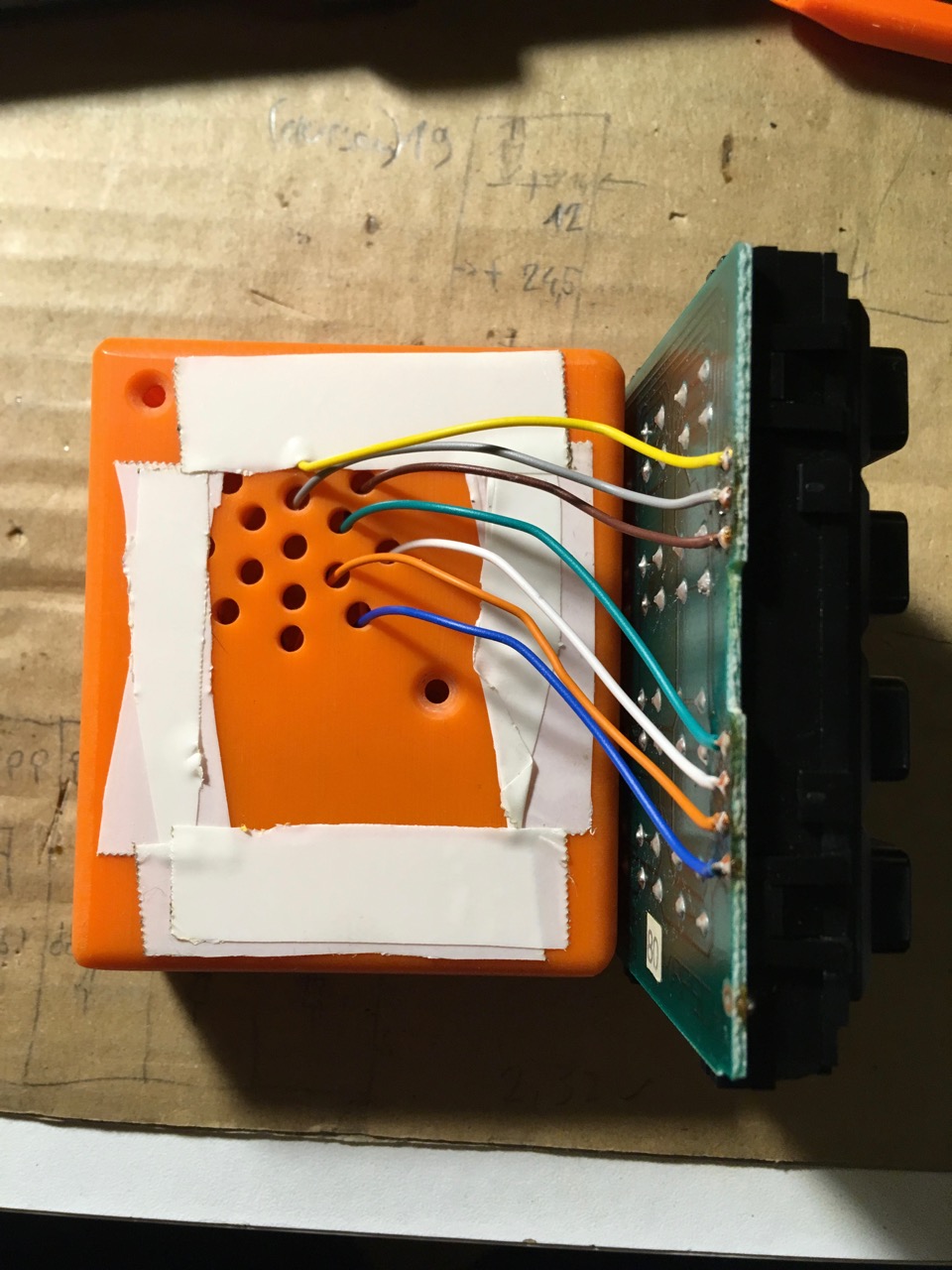
Before I started with writing code, I did some fitting to the case I was planning to put it in. I found this in my parent’s basement. Eventually I built it myself during my apprenticeship back in the 90ies. As far as I remember it should have become a battery powered radio and due to time reasons we never even started to build the electronics.
Writing code
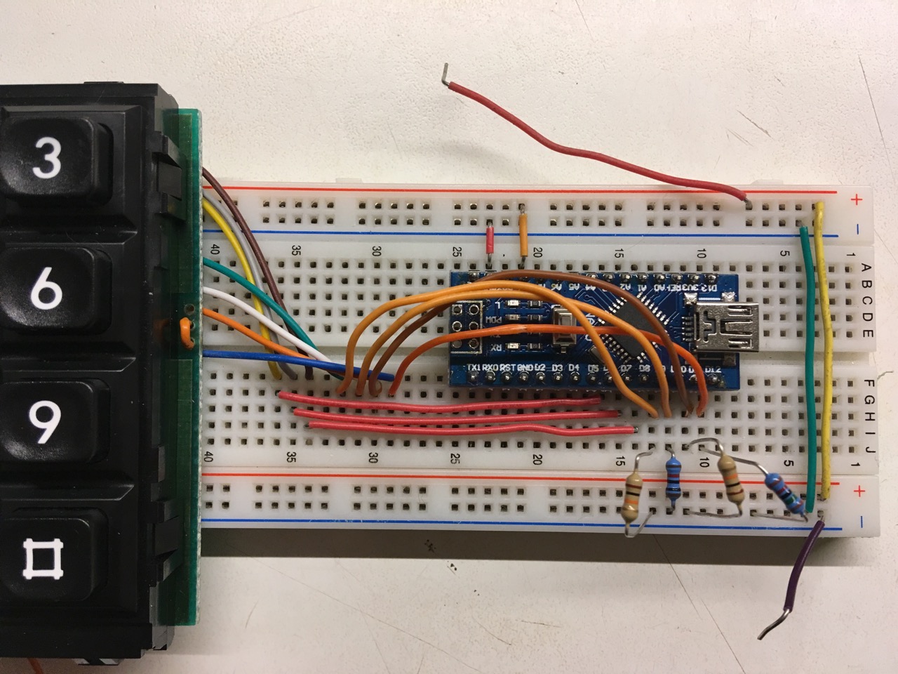
Breadboarding
Prerequisites
I won’t copy tons of code to here but leave it on github and post links to commits/diffs and whole code checkouts for copying and pasting.
I use some libraries because they make sense. They can be installed from the Arduino IDE “Library Manager”.
- advancedSerial - helps with debugging over the serial monitor, I think the original serial print and println commands are pretty uncomfortable to use.
- MIDI - send and/or receive MIDI messages via any serial port.
Test sketches
Let’s check if the matrix and our breadboarding setup works and we actually understand what we are doing here with this test sketch. Manually set one of the output pins to HIGH level in lines 36-38 of the program and see what happens on the serial monitor.
With this next commit I loop through the 3 outputs, set them HIGH, and see which of the input lines have received the HIGH (because a button was pressed). This is the whole file to copy and paste. Actually this is the whole magic about reading out the state of any matrix keypad.
You should see something like that on the serial monitor when pressing buttons. It tells you wich row and col IDs are HIGH at the moment:
yes it's high: 0 0
...
...
yes it's high: 2 3
Best practices
Read through the commit messages and the comments in the code to see what I was thinking
- store MIDI CCs in button array
- 3 different modes - my suggestion on how to easily switch between software emulated MIDI, just debugging and “real” MIDI. Helps with going back to coding and extending your controller later on without thinking to much.
- momentary press behaviour - I decided to program my controller so it sends out what is called a “momentary press”. It sends out a MIDI CC on message when a button is pressed and does nothing as long as you keep that button pressed. Only on releasing the button it sends out a MIDI CC off message.
- set debounce time - these values worked for me, a button press feels pretty responsive.
- make it low-active - saves the pull-down resistors. This is the final version for a native MIDI version. Read on, for a solution to make it work on any Non-USB-MIDI compliant Arduino. If you want to use the hairless MIDI bridge software, just change the mode to 1 here
Finalizing
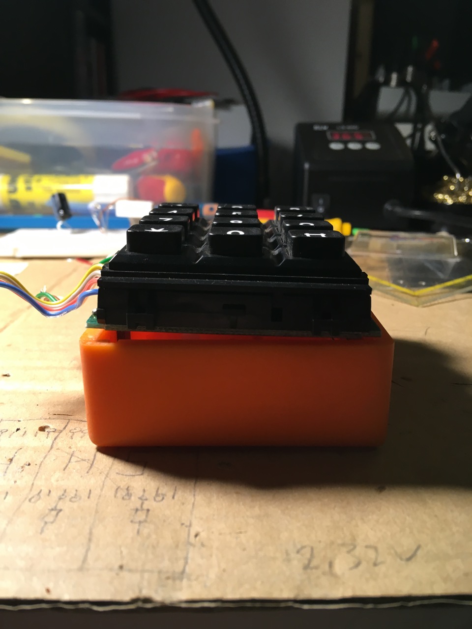
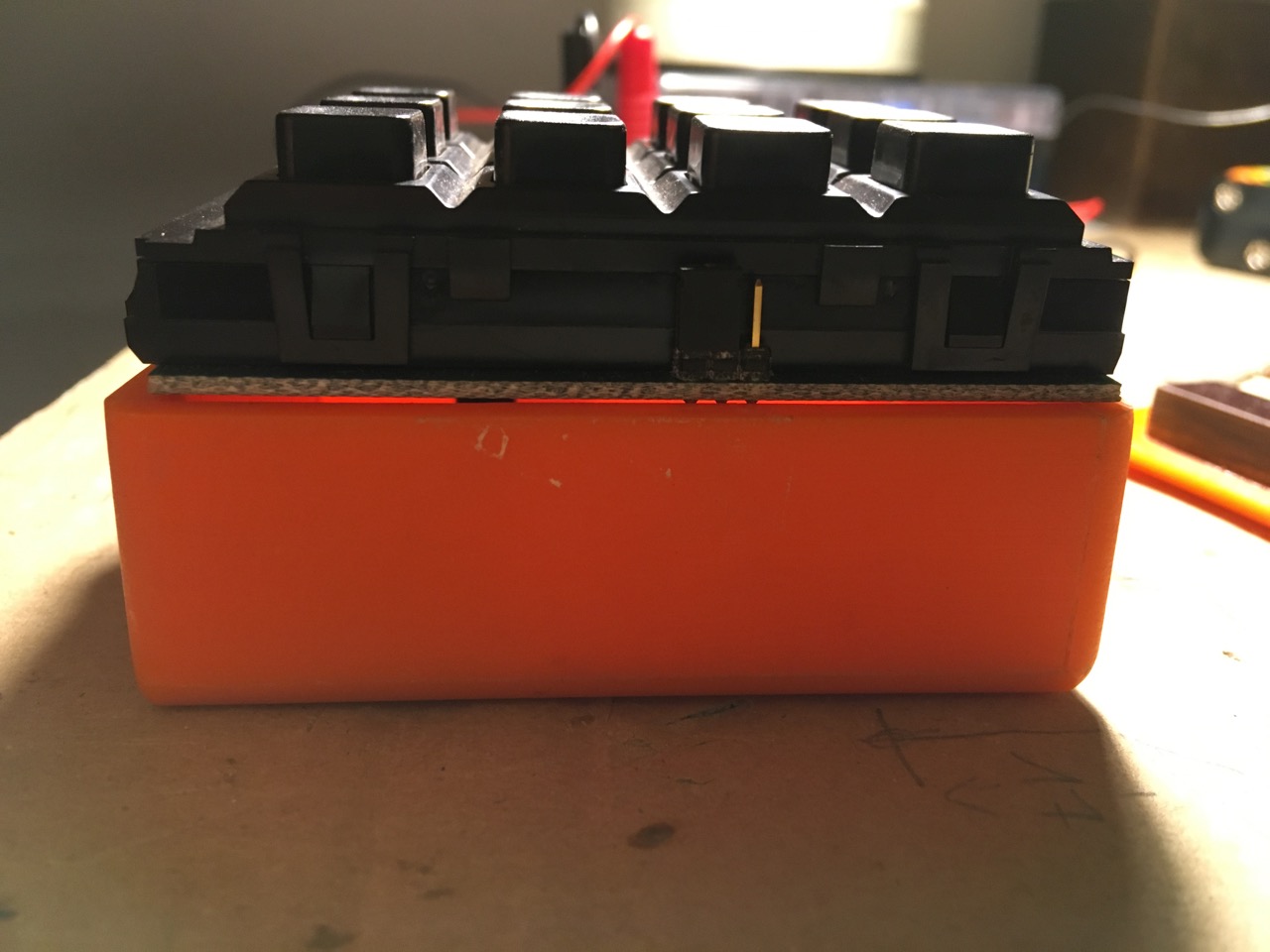
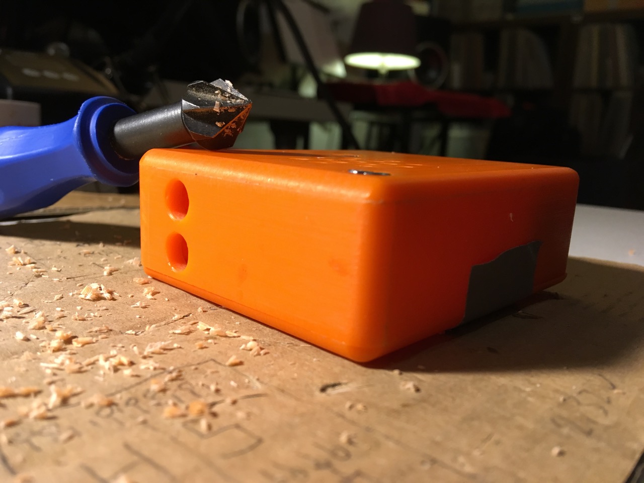
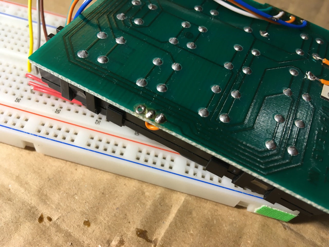
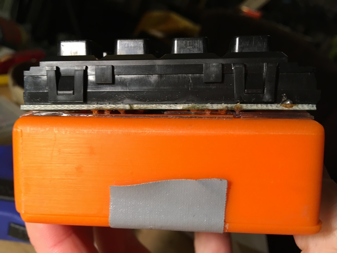
Mounting the keypad to the case
The cheapest USB-MIDI-Arduino available
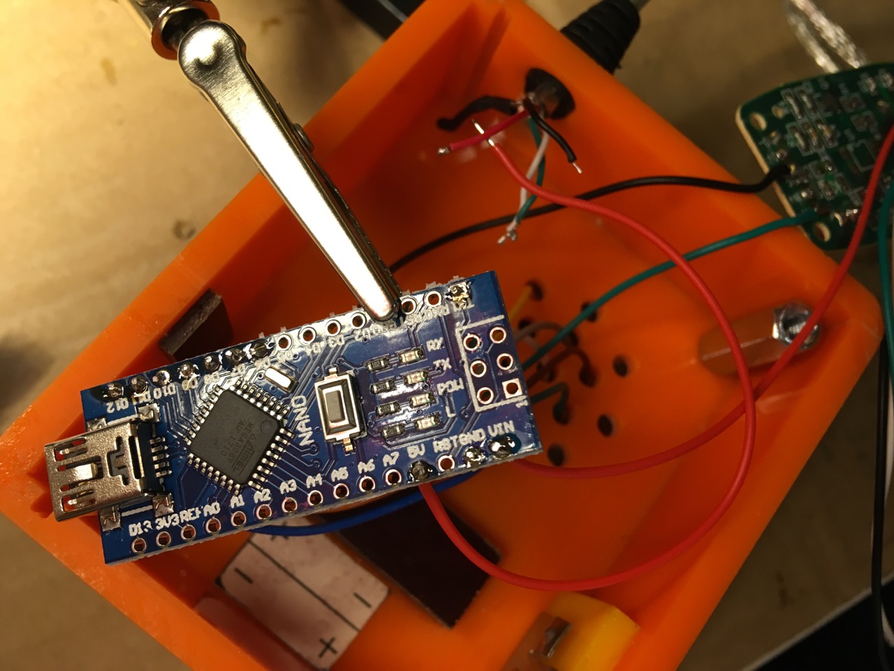
As mentioned at the very top of this post, most Arduinos are not capable of showing up as proper MIDI device in your computer’s operating system. If you are fine with using a software MIDI bridge like the hairless MIDI bridge, just look at the first picture in this chapter and you are done.
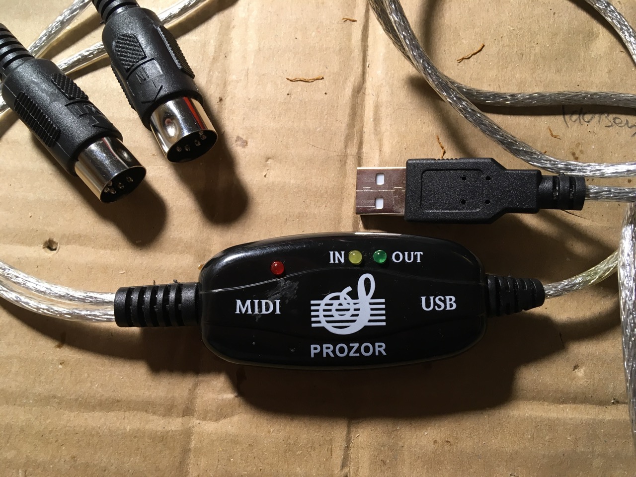
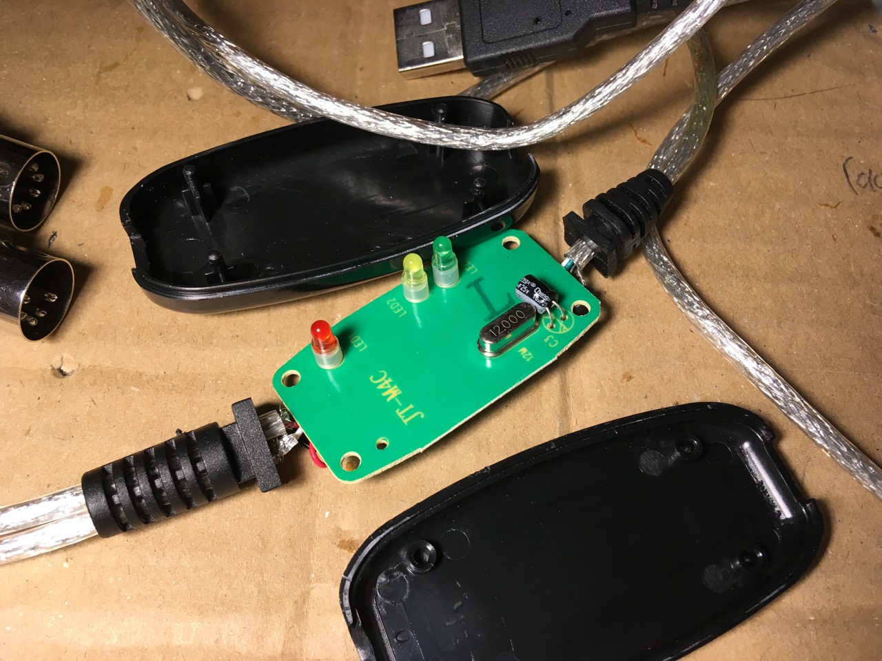
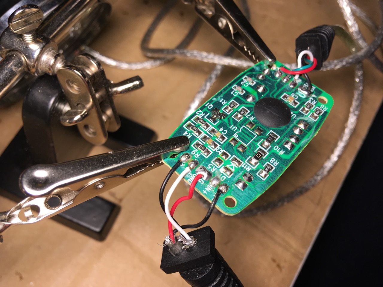
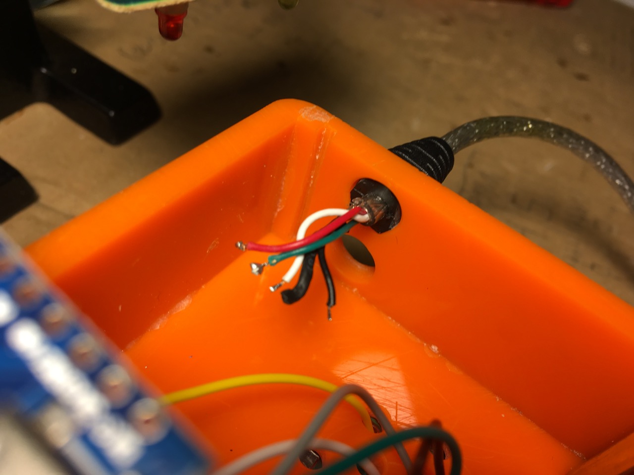
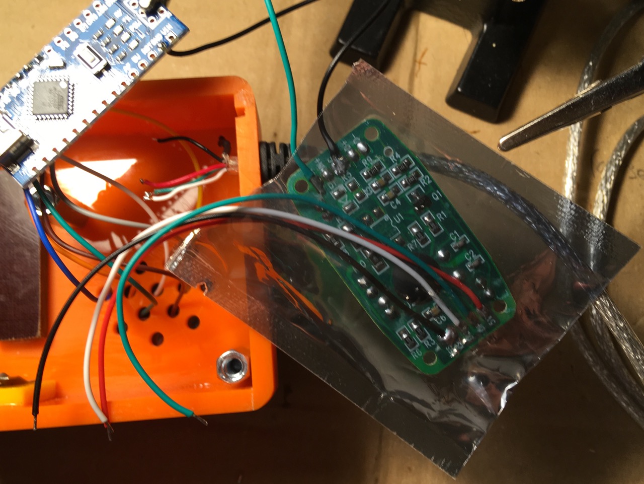
If it is not, one of the cheapest solutions around is to steal the electronics out of a USB to MIDI Adapter cable. You can get them in Europe for about 7-10 €. Certainly if you order them in China, a few pieces of them will cost you almost nothing. And btw: These cheap adapter cables are pretty useless for serious MIDI applications like controlling a synth from your your DAW. They are built so cheap, they literally loose data! Believe me, I measured it. But they are definitely good enough to be used for sending some knob or button movement aka some MIDI CC bytes. That’s only a tiny amount of data and my experience is that they handle that savely.
Testrun
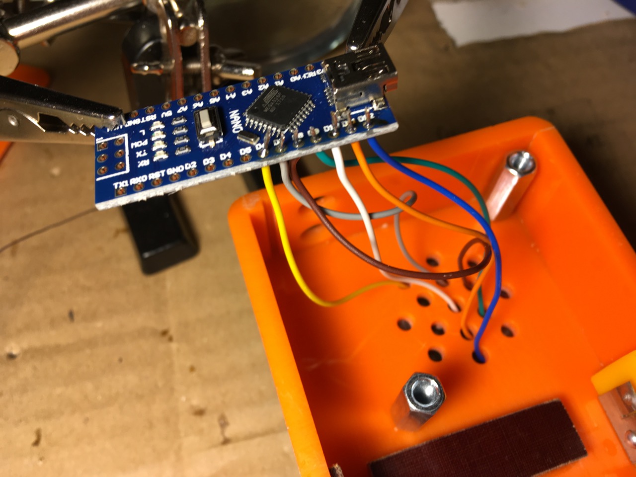
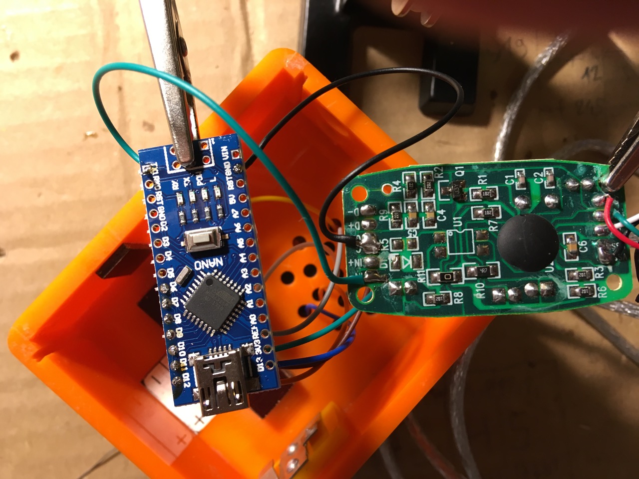
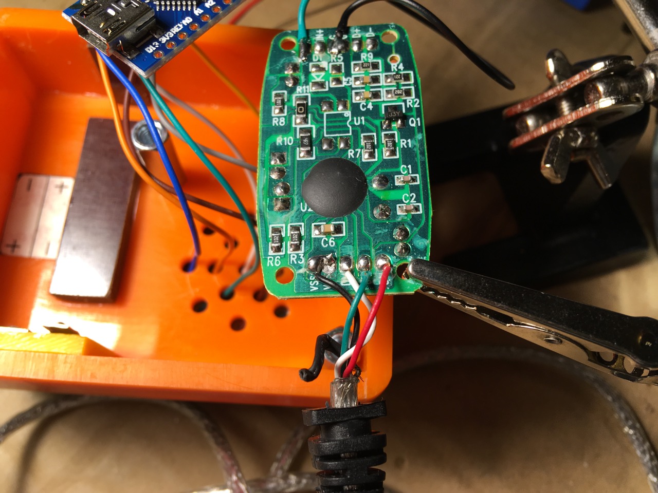
Now that we don’t have to use the hairless MIDI bridge anymore, we change the mode of the program to send native MIDI speed (31250 bps) out of the Arduinos TX1 pin:
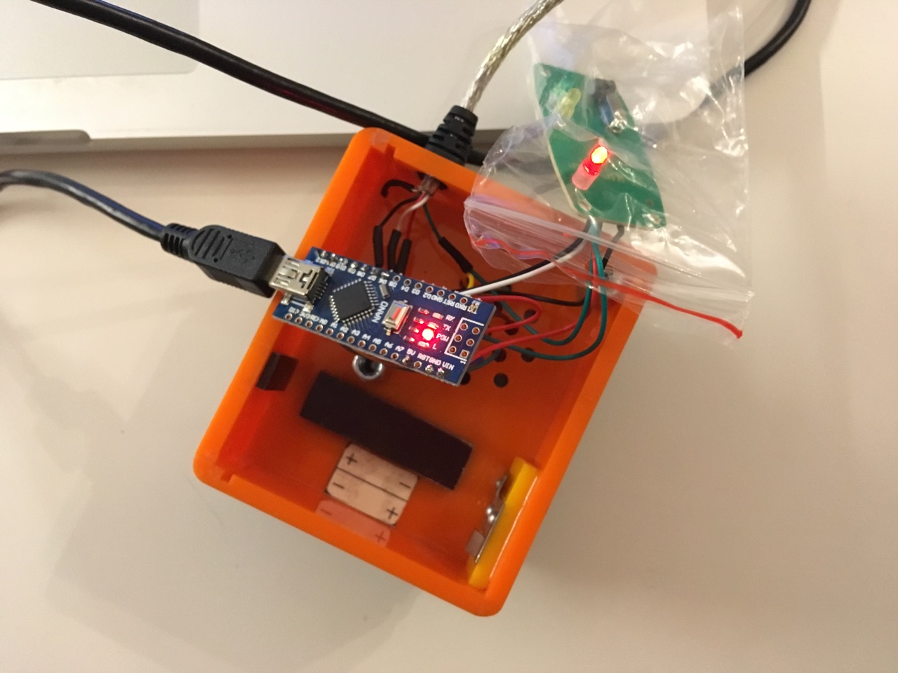
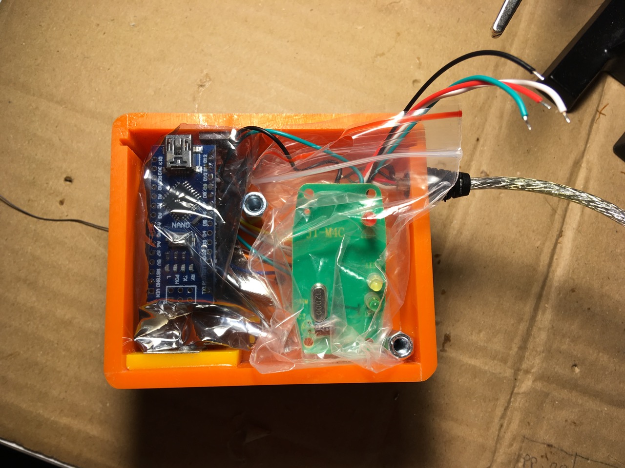
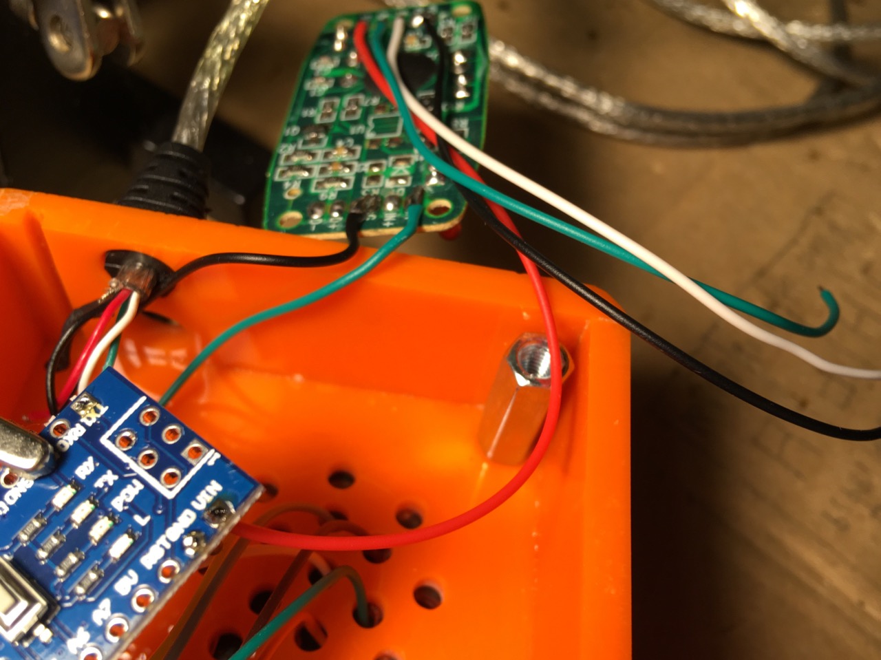
The Nano’s onboard LEDs and the Adapter-PCB’s MIDI-IN LED should blink shortly when MIDI data is transmitted from the controller.
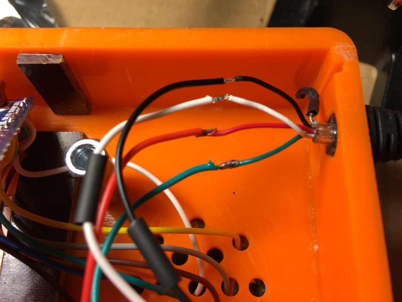
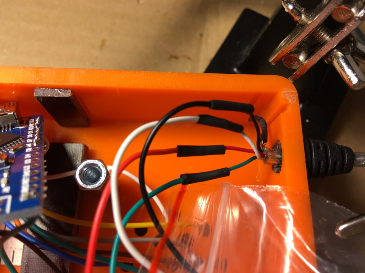
But what if I just want to use a classic MIDI cable?
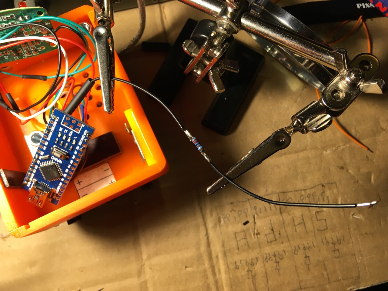
Just connect GND, +5V and TX1 pins of the Arduino to a 5-pin DIN-socket like described in this sparkfun tutorial.
The drawing on the bottom of this pic shows where the pins of your DIN jack should go:
- pin 4 -> 220R resistor -> +5V
- pin 5 -> 220R resistor -> Arduino TX1
- pin 2 -> cable shield -> Arduino GND
As you’d expect, just use an ordinary MIDI cable (jack-jack) to connect from your controller’s socket to the device you want to control.
Making it even fancier
I had 5 digital pins left on the Arduino Nano, let’s use them!
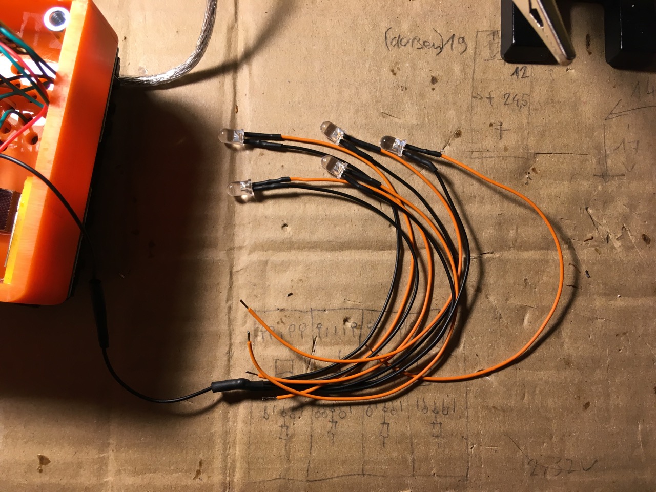
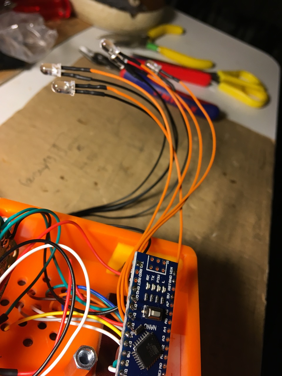
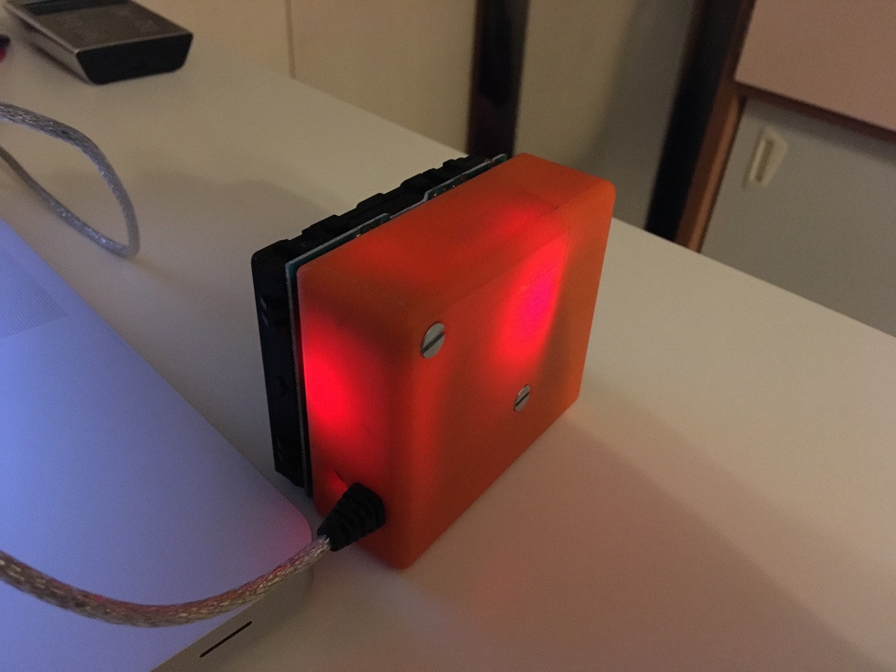
Blink on send addon
Just a little addition to the code: blink 5 LEDs when sending CC
Maybe using red LEDs would bring a more dramatic effect.

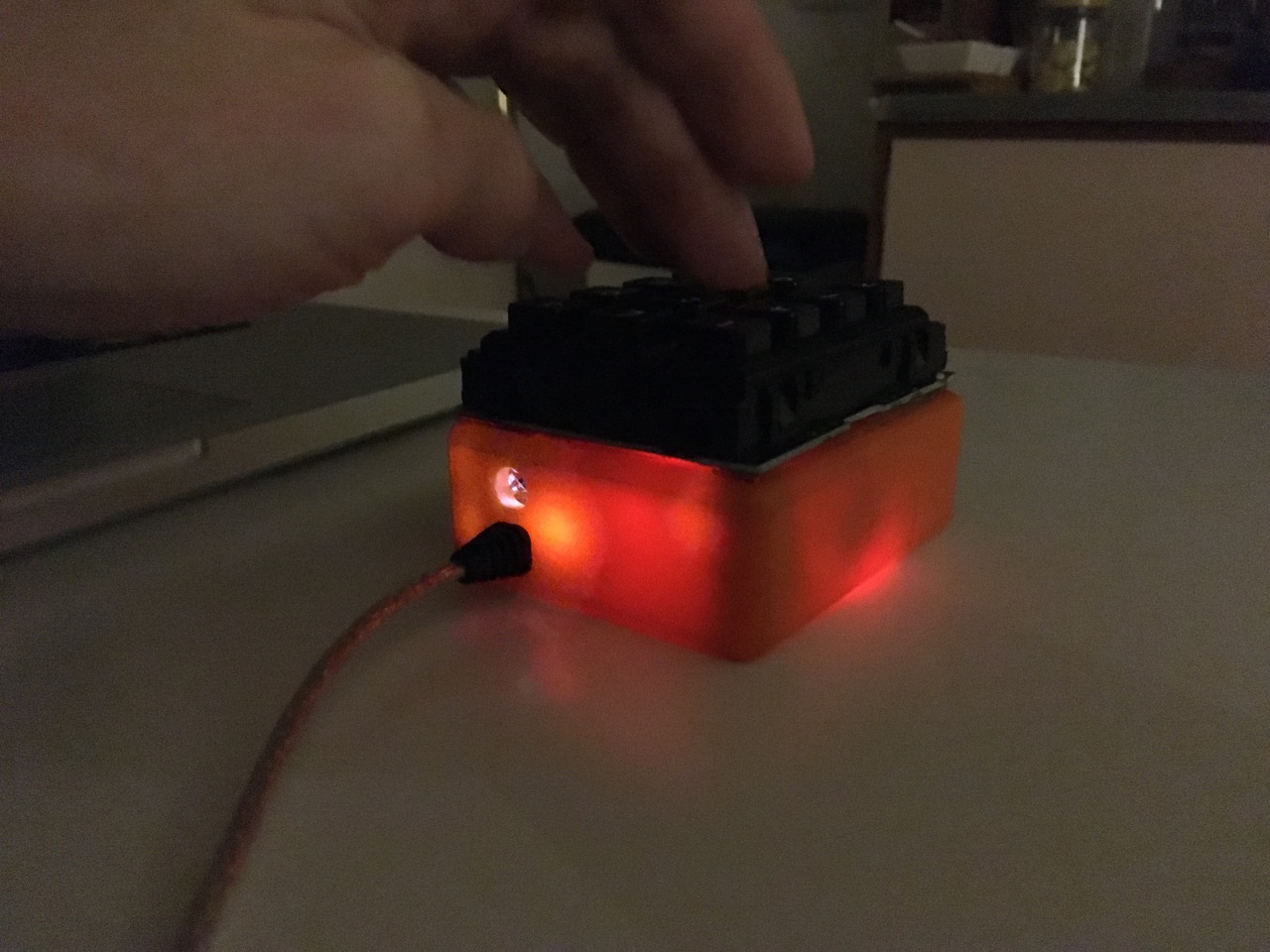
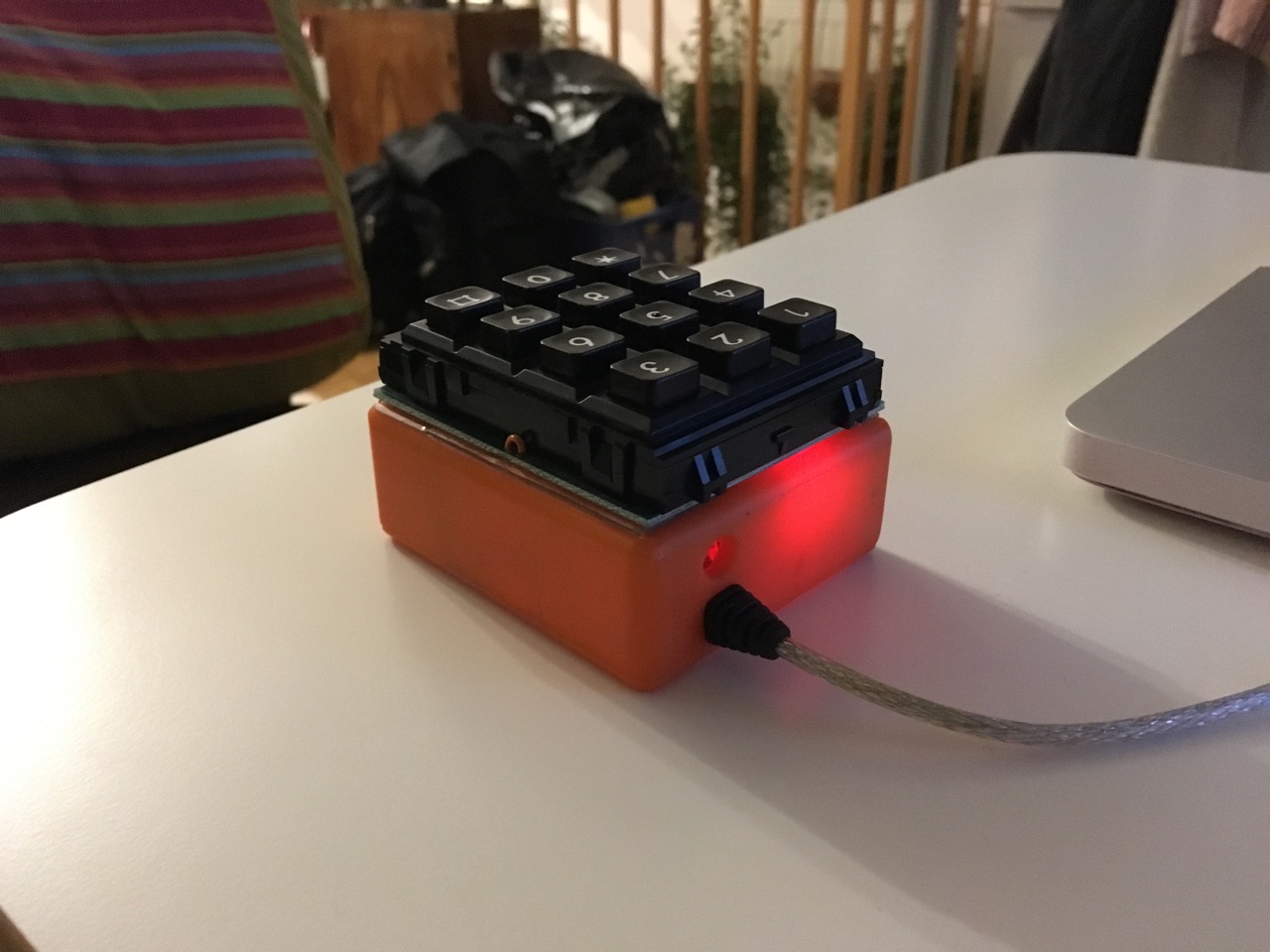
The final product

Using it
MIDI mapping in Ableton Live - The momentary-mode buttons behave differently depending on which controls they are mapped to:
- (mis)using buttons for dial type controls: as long as the button is pressed the dial is put to halfway up (we send MIDI CC value 64), when releasing it goes to 0 again.
- on/off controls like eg the mute buttons: as long as the button is pressed it’s unmuted, if released it’s muted again. For device on/off buttons the behaviour is the same.
- the solo buttons behaviour is different: press once - solo stays on - press again - solo stays off
Getting supplies
As usual I recommend supporting and buying from musikding.de, because it’s just well sorted and has good prices (first two links). For the MIDI adapter cables and Arduinos I have put together some links to cheap buys on amazon.de. If you like what you see on this blog please support me by using these links. I get a little nothing from amazon then ;-)
- 14 pin strip
- nice colored cases
- USB-MIDI Adapter cable 7€
- USB-MIDI Adapter cable 11€
- USB-MIDI Adapter cable 4€
- USB-MIDI Adapter cable 5€
- USB-MIDI Adapter cable 6€
- USB-MIDI Adapter cable 12€
- USB-MIDI Adapter cable 8€
- USB-MIDI Adapter cable 7€
- 3 x Arduino Nano 14€
- 3 x Arduino Nano 15€
- 5 x Arduino Nano 19€
- 5 x Arduino Nano 17€
- 5 x Arduino Nano 18€
- 3 x Arduino Nano 10€
- 1 x Arduino Nano 6€
- 5 x Arduino Nano 12€